
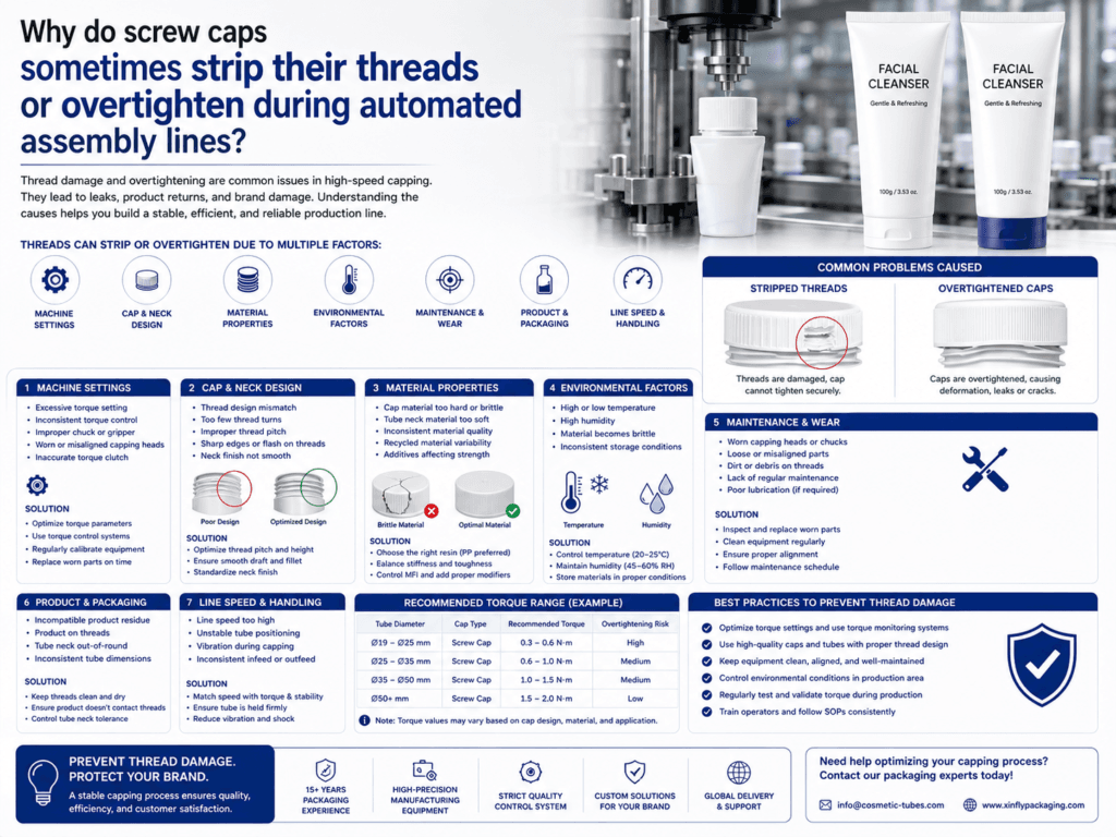
Screw caps can strip their threads or overtighten during automated cosmetic tube assembly when the capping torque, cap-thread design, tube-neck tolerance, material stiffness, alignment, and machine speed are not properly matched. The problem may appear as damaged threads, cracked caps, tilted caps, poor opening feel, leakage, or caps that consumers cannot easily remove.
In automated assembly lines, the cap is applied at high speed by a chuck, spindle, or torque-controlled capping head. If the system applies too much torque, starts the cap at the wrong angle, or uses caps and tube necks with poor dimensional control, the plastic threads can deform, cross-thread, or become permanently damaged.
Quick Answer
Screw caps usually strip or overtighten because of excessive capping torque, poor cap-to-neck thread matching, misalignment, high machine speed, inconsistent cap material, weak tube-neck strength, or insufficient torque control. The solution is to define a proper torque window, control neck and cap tolerances, test cap fit with filled tubes, and validate the automated line before mass production.
| Problem | Main Cause | Visible Result |
|---|---|---|
| Thread stripping | Torque too high or thread engagement too weak | Cap spins without locking, poor seal, damaged neck thread |
| Overtightening | Capping head applies excessive closing force | Consumer cannot open easily, cap stress, cracked cap |
| Cross-threading | Cap starts at an angle or tube is not centered | Tilted cap, leakage, damaged thread start |
| Cap cracking | Material too brittle or torque too high | Crack marks around cap skirt or thread area |
| Leakage after assembly | Cap not sealed correctly despite high torque | Formula leakage during storage or shipping |
Why Automated Assembly Lines Increase Thread Risk
Manual capping allows an operator to feel resistance and stop when the cap is tight enough. Automated capping lines rely on machine settings. If torque, height, pressure, speed, or alignment is incorrect, thousands of caps can be damaged before the problem becomes obvious.
- High-speed rotation: Fast cap application can damage threads if the cap is not aligned correctly.
- Fixed torque setting: One torque value may not work for every cap batch or tube-neck tolerance.
- Tube holder movement: If the tube is not stable, the cap may start crooked.
- Cap feeding variation: Caps may enter the chuck at inconsistent angles.
- Material variation: Slight differences in cap resin, shrinkage, or stiffness can change torque behavior.
Excessive Torque: The Most Common Cause
Capping torque is the rotational force applied to tighten the screw cap. If the torque is too low, the cap may leak or loosen. If the torque is too high, the cap can overtighten, strip threads, crack, or deform the tube neck. The correct torque window must be confirmed by testing the exact cap, tube neck, formula, and filling process.
| Torque Condition | Possible Result | Corrective Action |
|---|---|---|
| Too low | Loose cap, leakage, poor airtight seal | Increase torque gradually and verify leakage performance |
| Correct torque window | Secure seal with acceptable opening force | Use this range as the production standard |
| Too high | Thread stripping, cap cracking, difficult opening | Reduce torque and inspect cap/neck thread condition |
| Unstable torque | Some caps loose, some overtightened | Check machine chuck, cap feeding, tube holding, and tolerance variation |
Engineer’s note: A tighter cap does not always mean a better seal. Once the cap passes the correct sealing point, extra torque may damage the thread instead of improving airtight performance.
Cap and Tube Neck Design Factors
The cap and tube neck must be designed as a matched system. A good screw cap requires correct thread pitch, thread depth, thread start, sealing land, cap skirt height, neck finish, and dimensional tolerance. If the cap and tube neck come from different suppliers, fit testing becomes even more important.
| Design Factor | Risk If Incorrect | Recommendation |
|---|---|---|
| Thread pitch | Cap does not engage smoothly or strips easily | Match cap thread pitch with tube neck standard |
| Thread depth | Too shallow reduces holding strength; too deep may bind | Confirm by drawing and physical torque testing |
| Thread start | Cap starts crooked and cross-threads | Use clean thread start design and stable cap feeding |
| Sealing land | Cap may tighten but still not seal | Ensure the sealing surface is flat, clean, and dimensionally stable |
| Neck tolerance | Some tubes are too tight while others are too loose | Control neck diameter, thread height, and ovality |
Material Factors That Affect Thread Strength
Plastic cap and tube-neck materials must have enough toughness to resist high-speed capping. If the cap resin is too brittle, it may crack. If the tube neck is too soft, the thread may deform. If PCR material or special color masterbatch is used, torque and crack resistance should be tested carefully.
| Material Factor | Effect on Assembly | Quality Control Point |
|---|---|---|
| Cap resin stiffness | Too stiff or brittle may crack under torque | Choose suitable PP/PE cap resin and test impact resistance |
| Tube-neck softness | Soft neck threads may deform or strip | Review shoulder/head material and wall strength |
| PCR content | Material variation may affect torque consistency | Run batch-to-batch torque and crack tests |
| Color masterbatch | Some pigments may affect shrinkage or brittleness | Approve cap color with mechanical testing, not only appearance |
| Surface finish | Glossy, matte, or textured caps may change chuck grip | Adjust capping chuck material and pressure |
Machine Setup Problems
Even a well-designed cap can fail if the automated capping line is not set correctly. The most common machine-related issues include excessive chuck pressure, unstable tube holders, poor cap feeding, wrong capping head height, worn gripping parts, or no torque feedback system.
| Machine Factor | How It Damages Threads | Adjustment Direction |
|---|---|---|
| Capping head torque too high | Strips thread or overtightens cap | Set a verified torque range and monitor regularly |
| Chuck pressure too high | Deforms or scratches the cap | Use suitable chuck liner and reduce gripping pressure |
| Tube holder not centered | Cap starts at an angle | Improve tube cup alignment and holder stability |
| Cap feeder misalignment | Cap enters capping head crooked | Adjust cap chute, bowl feeder, and pick-up position |
| Capping speed too fast | Thread cannot engage smoothly before full torque is applied | Reduce speed or use controlled start torque |
| Worn capping parts | Torque becomes unstable | Replace chuck liners, belts, heads, and holders as needed |
Thread Stripping vs. Overtightening
| Issue | What It Means | Typical Root Cause |
|---|---|---|
| Thread stripping | The cap or neck thread is damaged so the cap cannot hold properly | Excessive torque, weak thread design, soft neck material, cross-threading |
| Overtightening | The cap is tightened beyond the ideal closing point | Torque setting too high, no stop control, cap friction variation |
| Cross-threading | The cap engages the neck thread at the wrong angle | Misalignment, unstable feeding, poor thread start, tilted tube |
| Stress cracking | The cap cracks after assembly or during storage | High stress from overtightening, brittle cap material, chemical exposure |
Formula and Filling Conditions Can Also Contribute
Although thread stripping is mainly mechanical, the filled formula and filling conditions can make the problem worse. If formula residue contaminates the thread or sealing land, the cap may not seat properly. If the tube is hot after filling, the neck and shoulder may be softer during capping. If the tube is overfilled, internal pressure can increase the closing load.
- Formula on the neck: Residue can increase friction or prevent proper cap seating.
- Hot filling: Warm tube necks may deform more easily during capping.
- Overfilling: Internal pressure can make the cap harder to close correctly.
- Oil-rich formulas: Some oils may reduce friction control or affect cap material over time.
- Foaming formulas: Pressure buildup may stress the closure after assembly.
How to Prevent Thread Stripping and Overtightening
| Prevention Method | How It Helps |
|---|---|
| Define a torque specification | Prevents both loose caps and overtightened caps |
| Use torque-controlled capping heads | Improves consistency across high-speed production |
| Match cap and neck drawings | Ensures thread pitch, depth, and sealing land are compatible |
| Improve tube and cap alignment | Reduces cross-threading and tilted caps |
| Control cap and neck tolerances | Prevents some units from being too tight or too loose |
| Test with real production speed | Confirms that the closure works under automated line conditions |
Recommended Tests Before Mass Production
| Test | Purpose | What to Check |
|---|---|---|
| Application torque test | Measures torque used to apply the cap | Overtightening, torque consistency, machine setting stability |
| Removal torque test | Measures how hard the cap is to open | Consumer opening comfort and overtightening risk |
| Thread engagement inspection | Checks cap and neck fit after assembly | Cross-threading, stripped threads, tilted caps |
| Leakage test | Confirms the cap seals correctly | Neck leakage, cap leakage, formula residue |
| Repeated open-close test | Checks thread durability during consumer use | Thread wear, cap looseness, seal degradation |
| Drop and compression test | Checks transport durability after capping | Cap cracking, loosening, leakage, shoulder damage |
| Aging test | Checks stress cracking and long-term closure stability | Cracks, torque change, leakage after storage |
Production Line Troubleshooting Checklist
| Symptom | Likely Cause | First Action |
|---|---|---|
| Cap spins but does not tighten | Stripped cap or neck thread | Reduce torque and inspect thread dimensions |
| Cap is tilted | Cross-threading or poor alignment | Check cap feeder, tube holder, and capping head height |
| Consumers cannot open cap easily | Overtightening or high removal torque | Lower application torque and test removal torque |
| Caps crack after assembly | High stress or brittle material | Review torque, cap resin, wall thickness, and storage conditions |
| Some caps leak but others do not | Torque variation, dimensional tolerance, or inconsistent cap feeding | Monitor torque distribution and inspect cap/neck tolerance |
Common Mistakes to Avoid
- Using maximum torque to prevent leakage: Too much torque can strip threads and create new leakage risk.
- Testing caps by hand only: Automated assembly creates different stress than manual capping.
- Ignoring removal torque: A cap may seal well but be too hard for consumers to open.
- Mixing caps and tubes from different suppliers without fit testing: Small thread differences can cause cross-threading or leakage.
- Skipping filled-tube testing: Formula residue, internal pressure, and hot filling can change cap behavior.
- Not monitoring torque during production: Machine settings can drift as parts wear or speed changes.
Best Practical Recommendation
For automated cosmetic tube assembly, the best solution is to treat the screw cap and tube neck as one engineered closure system. Confirm cap drawing, neck drawing, thread pitch, sealing land, cap material, tube head material, and dimensional tolerance before mass production. Then set a validated application torque and removal torque window based on filled leakage testing and consumer opening comfort.
For high-speed lines, use torque-controlled capping heads, stable tube holders, accurate cap feeding, and regular in-process torque checks. Do not increase torque blindly to solve leakage. First check cap fit, sealing land, thread engagement, formula residue, headspace, and tube-neck tolerance.
Summary
Screw caps strip their threads or overtighten during automated assembly because of excessive torque, poor cap-to-neck matching, cross-threading, weak material strength, high machine speed, unstable cap feeding, or inconsistent dimensional tolerance. The result can be damaged threads, cracked caps, tilted closures, poor consumer opening feel, or leakage.
To prevent this issue, brands and filling factories should define torque specifications, match cap and tube-neck drawings, control tolerances, optimize machine alignment, test at real production speed, and validate filled tubes through application torque, removal torque, leakage, repeated open-close, drop, compression, and aging tests.
Learn more: Caps & Closures, Screw Cap Tubes, Automated Tube Filling and Sealing Parameters, Screw Caps vs Flip-Top Caps for Facial Cleanser Tubes, Quality Assurance, Sample Development.
Need Screw Caps That Run Smoothly on Automated Lines?
Xinfly Packaging helps brands match screw caps, tube necks, thread design, sealing land, torque range, filling conditions, and automated assembly requirements to reduce stripping, overtightening, leakage, and cap defects.